Have you ever wondered how cables work? Or how a peripheral, such as a mouse, communicates with a host?
I never knew or even thought about it until I started this project. But it’s a fascinating question– especially if you consider that a wire can only have two states:
- Electricity is flowing
(1) - Electricity is NOT flowing
(0)
And yet, despite only having two states, we can transmit complex data such as mouse movement, clicks, or even entire files through cables.
How could this be?
The (simplified) answer is that… Devices toggle the power in the cable on and off at very high speeds and then use a pre-determined protocol that allows them to encode and decode these sequences of 0s and 1s into actual data.
Most of the time, we software developers, don’t need to concern ourselves with how any of this works. Because usually you’d use a hardware chip that handles all the nitty-gritty details of this communication.
All you have to do is ask the hardware chip to…
“Send this data… and notify me when the device sends something back.”
And the chip does all the work of toggling the electricity on and off and reporting the results back to you.
But in some very rare instances, it’s not that easy…
For example, when you want to use a device that uses THIS connector and protocol…
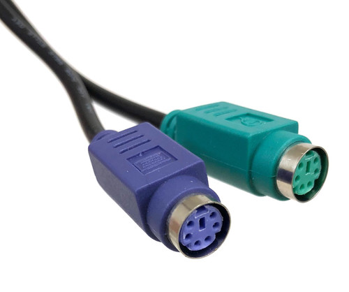
Yep… If you recognize these cables, it means you’ve been around computers since at least the mid-nineties. Back then, we were using keyboards and mice with these PS/2 connectors.
That was long before we started cursing at USB-A cables, that seemingly needed to be turned around AT LEAST two times before they fit in the plug.
And while PS/2 devices worked well, they were replaced by other more flexible and faster connectors and transmission protocols.
But one tiny device bucked the trend and continues to lead the resistance against modern connectors and protocols to this day.
Let me introduce you to one of the most controversial input devices in the history of computers: The IBM / Lenovo ThinkPad TrackPoint.

Some people love it, some people hate it… But most people don’t know what the hell that, little red nipple, is supposed to be.
Well, many keyboard nerds happen to LOVE TrackPoints, because they allow you to control the mouse without taking your fingers off the keyboard.
And as a hobby DIY ergonomic, split keyboard designer, I decided that I wanted one of these on my DIY ergonomic keyboard…
Fun Fact...
I never actually tried a TrackPoint before I developed this driver. It just seemed like a great addition to my keyboard and a fun project!
And now that I have tried it, I do understand why it has such a cult following and I’m very happy with my decision.
There were just two problems…
- Zmk, the firmware running on my keyboards, didn’t have a driver for TrackPoints
- DIY keyboard microcontrollers (“brains” for keyboards) had no hardware support for the old PS/2 protocol
But I didn’t let that stop me. Afterall… I am a software engineer…
And as software engineers, we don’t solve hard problems, because it IS easy… We solve them because the problems SEEM easy.
And then we get obsessed and addicted to solving them.
Of course, I am joking. But to be completely honest… That’s exactly how it started and here are some interesting details from the journey.
Spoiler Alert...
Eventually, I did succeed in adding a TrackPoint to my self-designed, ergonomic split keyboard.
It looks like this…
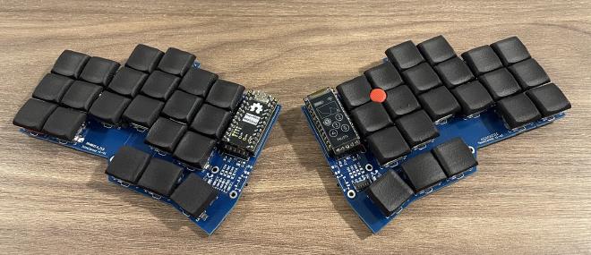
And you can find the code for the driver on GitHub.
A PS/2 mouse & trackpoint driver module for keyboards running the zmk firmware
Attempt #1: Bit-banging over GPIO #
I know, I know, right now you are probably thinking…
“Bit-banging? What kind of kinky stuff is this nerd into?!”
But I assure you, no keyboards or computers have been inappropriately touched in this project.
While the term “bit-banging” may sound odd, it really is the proper technical term for what I did.
Wikipedia describes it like this…
In computer engineering and electrical engineering, bit-banging or bit bashing is a term of art for any method of data transmission that employs software as a substitute for dedicated hardware to generate transmitted signals or process received signals.
Such software directly sets and samples the states of GPIOs (e.g., pins on a microcontroller) to transmit and receive, respectively, and is responsible for meeting all timing requirements and protocol sequencing of the signals.
In other words, in order to send data, we write code that turns electricity in wires on and off.
And to read data, the code observes the sequences of electricity flowing through the wires.
Whenever the electricity is flowing through the cable, the bit-value 1 is transmitted. And whenever there is no electricity, the bit-value 0 is transmitted.
A bit is the smallest data unit in computing, because it can only store two states: 1 or 0. So, it perfectly matches the two states an electrical circuit can have.
However, a sequence of bits can be combined into bigger units of data. Such as a byte, which consists of eight bits and can store 28 = 256 distinct values, such as 0-255.
For example, the command to tell the TrackPoint to start reporting mouse movement has the decimal value 244 (which is typically expressed using the hex system, which is 0xf4).
We can convert that to binary and get 11110100.
So, if we wanted to send the value 0xf4 to the TrackPoint, we would want to…
1:Turn the electricity on1:Keep it on1:Keep it on1:Keep it on0:Turn it off1:Turn it on again0:Turn it off0:Keep it off
In addition to sending the actual data, the code must also precisely follow the specification of the communication protocol that the device uses.
It does this by sending and observing certain sequences that indicate the start and end of the data transmission.
This way both our software and the device “speak the same language”.
I won’t bore you with the details, but the image below shows what the PS/2 data frame looks like and you can learn more about it on this page.
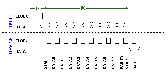
When I first read the specification, this seemed like a very straightforward and easy protocol to implement.
The project was going to be a piece of cake!
Boy, oh boy… was I wrong…
One of the biggest challenges was that this was my very first, serious embedded development project and I didn’t have the proper equipment for it.
I had no debugger and no way to see what was happening on the cable. I was essentially operating blind… Logging was my only debugging tool.
But after an entire week of hacking, I finally had a first, working prototype that could communicate with a disgusting, old, second-hand PS/2 mouse that I bought from Facebook Marketplace for the project…
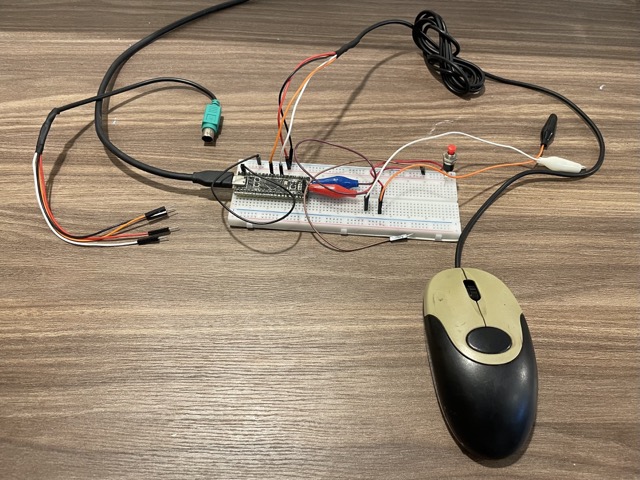
I finally had proof of concept that my dream of having a DIY ergonomic keyboard with a TrackPoint was feasible.
And so, I started calling all the computer repair shops in my area to try to find a broken Lenovo Thinkpad keyboard to extract the TrackPoint from it.
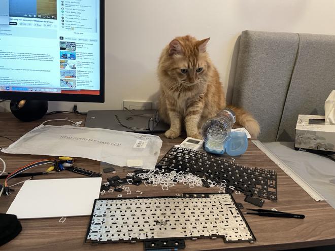
Fortunately, I wasn’t alone in this task. My trusted assistant, Dusty, was with me all along this journey. Not only was he my rubber duck, but he also was the product quality manager.
And with his help, I was finally able to extract the TrackPoint…
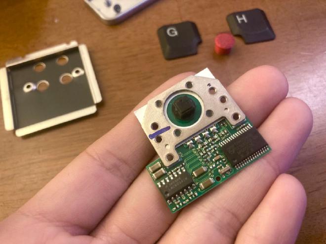
After a few more days of hacking the TrackPoint was working well enough for me to publish the code for others to test.
Together with this demo video:
Once this was done, I put the firmware development aside and turned towards designing my keyboard with the integrated TrackPoint.
The result of that effort was this design…

But once I started using the TrackPoint full time…
I realized the microcontroller was too slow for the TrackPoint #
During my initial development, I made the fatal mistake of using a different microcontroller for the development process than the one that’s most commonly used in the DIY ergonomic keyboard community.
In my development environment, I was using the STM32-based blackpill that has no Bluetooth support and is quite power hungry. But on keyboards, we typically use a wireless, nrf52-based nice!nano controller.
While the code worked perfectly on the blackpill, the nrf52 was sometimes too slow to handle both the Bluetooth connection as well as the data the TrackPoint was sending.
This led to infrequent, but extremely disruptive jerks in mouse movement and accidental clicks.
PS/2 operates at a frequency between 10 kHz and 16.7 kHz. In comparison, even the fairly old USB 2.0 operates at 480 MHz. That’s 28,000 times faster than PS/2.
But while PS/2 is quite slow compared to more modern protocols, it still toggles the electricity in the wires on and off at a speed of almost 15,000 times PER SECOND.
My original PS/2 GPIO bit-banging driver used GPIO interrupts.
This means that every time the TrackPoint toggles the electricity on or off, the GPIO controller woke up the CPU from its idle state to record the newly transmitted bit.
TrackPoints typically send a new bit of data every 70 microseconds, but the nrf52 CPU sometimes took over 100 microseconds to handle Bluetooth-related interrupts.
This meant that my driver wasn’t able to “catch” all of the bits the TrackPoint was sending.
On top of that, the PS/2 protocol has very, very basic data integrity checking. This meant that it oftentimes wasn’t possible to detect when an error in the transmission occurred.
I spent dozens of hours trying to look for workarounds, optimizations, and ways to prioritize my driver over the other processes.
But none of them worked well enough.
So, …
A radically different approach was needed… #
I decided to try to find a way to not use the CPU at all.
Modern microcontrollers have hardware support for a lot of transmission protocols, such as SPI, I2C, and UART.
My plan was to find a protocol that was as close as possible to PS/2 and then try to emulate PS/2 on top of one of these protocols.
This would offload as much of the processing as possible to one of these hardware chips.
I hoped that this way the CPU would only have to be woken up once larger chunks of data have been received instead of for each single bit.
This would lead to better performance and perhaps also better battery life.
To better understand the following attempts, please…
Let me introduce a few more details on how data is transferred through cables #
There are many different protocols for the transmission of data, such as PS/2, SPI, I2C, and UART.
One of the big differentiators between these protocols is how they synchronize data.
For example, imagine the TrackPoint transmits the value 0xFF (11111111) to the host. Electricity would flow through the wire for all 8 bits.
But how would the host know how many 1s were transmitted if the state of the data line never changed?
Some protocols, like PS/2, use a second wire, called the clock line, for that. Whenever the clock line switches from 1 to 0, the host reads the bit from the data line.
Other protocols, like UART, use timing to synchronize the transmission. Both devices must agree on a frequency at which the data will be written and read from the data line.
Then there’s the question of how the data frame is structured.
The data frame in a transmission defines what additional bits are transmitted as part of the protocol to indicate the start, end, error checking, etc., of a transmission.
On top of that we need to consider how many wires or pins are used. Some protocols use just one wire to transmit the data for both host-to-device and device-to-host transmissions, while other protocols use separate wires for each.
So, after a lot of research and brainstorming with the other guys on the zmk discord.
I started working on…
Attempt #2: PS/2 over SPI #
My initial attempt was to use SPI because, like PS/2, SPI uses a clock line to synchronize the data.
And it doesn’t require a data frame structure for the transmission.
My idea was to use SPI to read both the 8 data bits, as well as the 4 additional bits for the data frame.
While SPI sounded perfect in theory, I couldn’t get it working. It always forced the TrackPoint into an endless loop of sending seemingly random data.
On top of that, I realized that the nrf52 SPI controller only allows you to read data in 8-bit-sized chunks. But our full PS/2 data frame is 12 bits.
This means if the TrackPoint sends an odd number of bytes, we won’t be able to read all the data until the TrackPoint starts sending data again.
So, I decided to abandon this attempt.
Perhaps there was a way to overcome these challenges and make it work, but I wanted to explore other options to see if they would work better first.
So, I moved on to…
Attempt #3: PS/2 over UART #
UART is a protocol that at first glance doesn’t seem to have a lot in common with PS/2.
The only similarity is that it allows you to use the same data frame structure as PS/2.
But unlike PS/2, UART uses two separate wires for device-to-host and host-to-device transmissions.
And even worse, UART doesn’t use a clock wire to synchronize the data. Instead, the host and device must agree on a frequency (baud rate).
That’s a pretty big problem, but it gets EVEN worse… you can’t set any arbitrary frequency. You have to pick from one of the 18 allowed rates.
The PS/2 protocol specifies that the allowed frequency is between 10 kHz and 16.7 kHz. And the rate is decided by the TrackPoint and not by us.
We’d need to have A LOT of luck to have a match.
So, I pulled out my logic analyzer and started measuring the frequencies of all the TrackPoints I had.
All of them were toggling the electricity on and off approximately every 67us, which corresponds to a baud rate of 14,925.
The closest supported baud rate by the UART chip, in the nrf52 microcontroller, is 14,400.
Wow, that’s a difference of just 3.65%… Could we really be so lucky that this would work?
A few hours later, my terminal printed the two magical values I was hoping to see: 0xaa 0x00.
That’s the sequence a PS/2 mouse reports when it is connected successfully. And I received the data using the nrf52’s UART chip.
Even though the tech stars aligned for us and we got very lucky on the receiving end, this was just the beginning and there were many more challenges to solve.
The biggest one was that PS/2 uses just one wire for both sending and receiving data. But UART expects to have two separate wires. I had to come up with a way to switch the pin configuration whenever we switched between reading and writing.
On top of that, the UART implementation on the nrf52 chip ended up not fully supporting the PS/2 data frame.
So, I was only able to use it to read, but not write data. I ended up using the UART chip for reading and GPIO bit-banging for writing.
While bit-banging was too slow for reading, it works well enough for writing because we send data to the TrackPoint very infrequently.
And whenever the transmission fails, the TrackPoint clearly reports to the driver that the transmission failed so that we can re-send the command.
The biggest reason this new implementation was needed, was because the nrf52 CPU couldn’t keep up with the amount of data the TrackPoint was sending.
But now that the bulk of this data was pre-processed by the UART chip, the communication is flawless.
Conclusion #
Congratulations for making it this far.
I hope it was an enjoyable and perhaps even educational read for you. If you’d like to give my TrackPoint driver a try or just want to check out the code, you can find it on my GitHub:
A PS/2 mouse & trackpoint driver module for keyboards running the zmk firmware
And you might be interested in some of my other TrackPoint related projects, such as…
Scripts to generate keycaps with a cutout for a trackpoint
Scripts to generate 3D-printable models that increase the height of Lenovo TrackPoints to make them usable on ergonomic keyboards.
If you have any comments or questions, feel free to find me on the zmk discord server in the #pointing-devices channel.

